Using 3D Printer LCD module RGB MiniLCD12864V3 Part 2 LCD u8g2
Using 3D Printer LCD module RGB MiniLCD12864V3 Part 2 LCD U8G2
Pins Required by LCD
In part1 we have an introduction for this miniLCD12864V3 module.
Part1 :
https://superdiyprojects.blogspot.com/2022/10/using-3d-printer-lcd-module-rgb.html
Using 3D Printer LCD module RGB MiniLCD12864V3 Part 1 Intro
The major part of this module obviously is the LCD, it's 2.2inch size and has RGB backlight.
2.2inch is quite a good size, not too large and not too small.
To drive it, we need to connect below pins to MCU:
EXP1
Pin8 LCD_EN optional, keep in GND, this works as well
Pin7 LCD_RS (DC data/command) must connect to MCU
Pin6 LCD D4 Reset, optional, better to connect to MCU when in development phase, so it's easier to reset the LCD.
PIN5 LCD_D5 RGB data, mandatory, without RGB backlight working, we cannot see anything on LCD screen.
Pin2 GND
Pin1 5V
EXP2
Pin9 SPI_SCK SPI SCK, must connect to MCU
Pin5 SPI MOSI, must connect to MCU
The rest Pins are not needed for driving LCD.
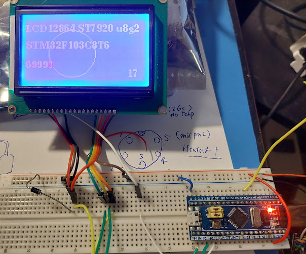
MCU connection
Software Side
STM32CUBEIDE Setting
In Stm32cubeIDE, set the pin options as above picture.
Set as GPIO output for RGB_Data, LCD_DC, LCD_RESET, LCD_CS
Set SPI as below picture. (We will use hardware SPI instead of software SPI)
Transmit Only Master because STM32 only need to send data to LCD, and not the other way.HW NSS ( PB12 ), in our test, we set it software, so we can control it by software code. In future, if we want to control LCD and SD together, we can. They share the same SPI bus, when we send data to LCD, we pull LCD CS low, SD CS high; when we send data to SD card, we pull LCD CS high and SD CS low.
( When we only need to control LCD, we can also change the hw NSS signal to be "HW output", so software code doesn't need to care about this gpio pin.)
I also tested spi speed Prescaler 16(2Mbit) , 8(4Mbit) and faster, it also works pretty well.
Clock Polarity CPOL=Low and CPHA=1 edge. Important.
If set it wrong, it may work, but signal integrity is bad...it causes a lot of strange problems.
LCD Backlight
Before we do anything for the LCD, we must turn on the RGB backlight, this module can only use RGB backlight, we cannot easily put a 5V to light it up...so, this could be a little bit challenging.
But in a previous post, I have done a RGB with WS2811 test, so, this should be easily done now.
https://superdiyprojects.blogspot.com/2022/10/stm32f103c8t6-bluepill-controls-rgb-led.html
Stm32F103C8T6 bluepill controls RGB LED WS2811 IC non-DMA method
There are also quite a lot writing in Internet about the same topic, however most of them are using DMA, this makes things necessarily complicated, and DMA is not needed in our application. Since we only need it for backlight, just need to turn it on and forget, so some simple GPIO write high and write low is good enough.
WS2811is quite a complicated project itself...so this post won't discuss more about it, we can simply use the class file in the above test and done.
super_rgbled_ws2811.h and super_rgbled_ws2811.cpp
Before we turn on the RGB backlight, we cannot see anything on the LCD screen
rgbled.rgb_led_on(128,128, 128);
U8G2 lib
It's easy to just use U8G2 to work with the LCD screen and draw text and graphics.
As usual, to make U8G2 to work with any LCD, we need to define two function and make a right constructor.
u8x8_byte_4wire_hw_spi callback and u8x8_stm32_gpio_and_delay_cb.Note the function name is not important, we only need to pass the name to constructor.
GPIO and delay
I believe most of the delay functions are useless, but the reset is needed.
Start init the LCD using U8G2
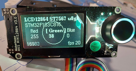
Just like that, we can write text and draw on the LCD screen using U8G2.


Comments
Post a Comment