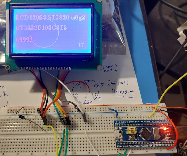
STM32 and U8G2 to draw on LCD12864 Using hardware SPI
STM32 bluepill and U8G2 to draw on LCD12864 Using hardware SPI
Since there are not a lot of info about this on Internet, so I am making this guide.
We can see some info/guide or example about using Arduino board, or Arduino IDE, or Software SPI to draw using U8g2.
But in this guide, we will use hardware SPI, Stm32 chip, and use Stm32CubeIDE to draw.
Keyword here:
Bluepill, blackpill, u8g2, LCD12864(5V, works with 3.3V stm32 MCU), hardware SPI communication, Stm32CubeIDE.
Part List in the test:
LCD12864 screen, Bluepill dev board(stm32F103C8T6) or Blackpill dev board( stm32F401CCU6), 5V power supply, stlinkV2 device to flash or debug.
Low cost LCD12864 (ST7920), it's large, and good resolution(128X64), cheap. It has a lot of pins for parallel connection, DB0 DB1 DB2...DB7, but who has so many pins to connect?? In fact, this LCD can support SPI connection, it only need 2pins to MCU: MOSI and SCK, CS and RESET is optional, no need to connect to MCU.
In SPI mode, pin usage:
Pin 5 RW : MOSI , SPI MOSI. Must connect to MCU.
Pin 6 E : CLK , SPI SCK. Must connect to MCU.
Only above two pins are needed to connect to MCU for SPI connection, so using this LCD with MCU is very easy. We can skip all the DB0 to DB7 pins, MCU can save a ton of GPIO for other higher purposes.
Pin 1 Gnd
Pin2 VCC 5V, but we could or probably should lower the voltage to 4.3V for multiple purposes, more on that later.
Pin 4 RS : CS, SPI CS (Chip select), can always pull high to enable, or connect to MCU, optional. For this test, to make things easier, it can be pulled up. according to the datasheet of the ST7920 page 26
When connecting several ST7920, chip select(CS)..... For a minimal system with only one ST7920 and one MPU, only SCLK and SID pins are necessary. CS pin should pull to high.
Pin 15 PSB : Pull to Gnd to enable SPI mode. ( or, pull high to enable parallel mode, if your MCU has a ton of gpio output to waste.)
Pin 17 Reset : when LCD is first powered on, reset pin must be first pulled low for a while then pull high to do a proper reset, otherwise may have garbage on screen. Can connect to MCU, use software code to pull down then pull high when first power on. or, use hardware solution: resistor and capacitor. To reduce the component we need for this test, we use MCU solution to save the resistor/capacitor and wires.
Pin 19 BLA : back light power, 5V power (or 4.X V)
Pin 20 BLK : back light power, Gnd.
Blue pill STM32F103C8T6 dev board. Once it's very cheap but now the price is getting higher and higher, and full of clone, so a better choice today is to buy Black pill STM32F401CCU6, about the same price and much faster and more ram/flash, but we still use bluepill in this test, yet it should work almost the same for black pill devboard.
Attention before wiring and power on: 5V could damage STM32.
Hardware Connection
Why use a diode for the LCD, reasons below:
LCD contrast adjustment
Software setup:
Stm32CubeIDE
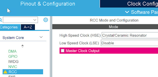
Then choose below settings for SPI2 and GPIO: SPI2_MOSI, SPI2_SCK, LCD_RESET. ( use USART_TX2 if you want to use usart debug output, or ignore). May add a label for the reset pin - LCD_RESET for easy use.
Note, Do NOTdefine PB13 and PB15 as usual GPIO, that is for software mode (using software to toggle GPIO to send data). We use hardware SPI mode here, so just leave them as is.
Important, change below settings for SPI2:
About SPI Speed:
Software and Coding:
Step1 Reset LCD (only when stm32 is just power up)
u8g2 u8g2 in github u8g2 is a GUI API for MCU to use.
uint8_t u8x8_stm32_gpio_and_delay_cb(U8X8_UNUSED u8x8_t *u8x8,U8X8_UNUSED uint8_t msg, U8X8_UNUSED uint8_t arg_int,U8X8_UNUSED void *arg_ptr) {switch (msg) {case U8X8_MSG_GPIO_AND_DELAY_INIT:break;case U8X8_MSG_DELAY_NANO:u8g_hw_port_delay_ns(arg_int);
2 Very important: define the 2nd callback function, this is for spi data transmit:
we call the STM HAL SPI transmit function HAL_SPI_Transmit here.
uint8_t u8x8_byte_3wire_hw_spi(u8x8_t *u8x8, uint8_t msg, uint8_t arg_int, void *arg_ptr) {switch (msg) {case U8X8_MSG_BYTE_SEND:HAL_SPI_Transmit(&LCD_SPI, (uint8_t*) arg_ptr, arg_int, 10000);break;
3 Define a user class using above two call back functions
class U8G2_ST7920_128X64_F_STM32_HW_SPI: public U8G2 {public:U8G2_ST7920_128X64_F_STM32_HW_SPI(const u8g2_cb_t *rotation = U8G2_R0) : U8G2() {u8g2_Setup_st7920_s_128x64_f(&u8g2, rotation, u8x8_byte_3wire_hw_spi, u8x8_stm32_gpio_and_delay_cb);}};
Explanation about some key points:
u8g2_Setup_st7920_s_128x64_f : the LCD12864 is using st7920 ic, since stm32 has a ton of ram, bluepill has 20KB sram, so we can easily give 1K to u8g2 ( _f function takes 1kb, there are also _1 and _2 simular functions use less RAM, probably arduino should use it). 128 Dot X 64 rows, one byte takes care of 8dots, so it uses 128/8X64=1024Bytes =1K.
u8x8_byte_3wire_hw_spi : the call back function we defined above, it's responsible for transmitting data to SPI.
u8x8_stm32_gpio_and_delay_cb: the other call back function we defined above, mostly for delay for our platform.
Then define our special u8g2 for stm32 hw spi instance
U8G2_ST7920_128X64_F_STM32_HW_SPI u8g2;
Then we can use our u8g2 to init and draw stuffs, and finally send to LCD.
Init steps:u8g2.initDisplay();
u8g2.setPowerSave(0);
Drawing steps
u8g2.clearBuffer();
u8g2.setFont(u8g2_font_ncenB08_tr);
u8g2.drawStr(0, 12, "LCD12864 ST7920 u8g2");
Finally send to LCD
u8g2.sendBuffer();
We need to put the drawing steps and sendBuffer() steps inside the main while(1) loop.
Go to here to see the full source code in github.
bluepill_LCD12864_u8g2 hardware SPI
files worth noting:
stm32_u8g2_lcd12864.cpp ,
stm32_u8g2_lcd12864.h
my_main.cpp
I use my_main.cpp to use C++, and my_main.cpp won't be overwritten by stm32 IDE automatically everytime I change setting.
More setting about stm32cubeIDe and u8g2.
we also need to copy the whole u8g2 folder inside the project's folder, since the IDE need u8g2's source code to compile, and it cannot choose a source folder outside of the project.
also the include path need to point to the u8g2.csrc is needed for header files, and cppsrc is needed for cpp project,
see below setting screenshot.
Please check the below video see how to actually works.
https://youtu.be/fgs0LIRNCDI
About speed and screen FPS
I have measure each sendBuffer() call takes 43ms, so one second can have at most 23frames, with some simple drawing and counter, the refresh rate dropped to 16frame per second as shwon in the video.
Is there a way to improve the speed?
the bottleneck is at the SPI speed, as mentioned above, if we lower the system speed then we can use a higher SPI speed (about 1Mbit), but the LCD doesn't work well at higher speed (1.1+ Mbit/s etc).
I have tested with SPI prescaler X32 (instead of 64) and with slower system speed 64Mhz, the FPS can be above 20 ( instead of 16).
We will explore more with Stm32's DMA feature to help with the speed.


Comments
Post a Comment