Stm32F103C8T6 bluepill controls RGB LED WS2811 IC non-DMA method
STM32F103C8T6 bluepill controls RGB LED WS2811 IC using non-DMA method
IDE: STM32CubeIDE
MCU: stm32F103C8T6 bluepill or black pill (STM32F401CCU6)
Category: RGB LED
IC: WS2811 ( Using a RGB LCD Screen, it has 3 RGB Leds, 3 WS2811 ICs)
Oscolliscope: useful and helpful

Intro
There are quite some tutorials in Internet about the topic, however many of those are using DMA method.
DMA is very useful in many use cases however not in mine, so I decided to investigate the non DMA method. I want to simply toggle GPIO to send the correct signal to the IC to make it work.
WS2811 is a RGB IC, each IC controls one RGB LED (Neopixel ?), for example if we have 3 RGB LEDs, we need 3 WS2811.
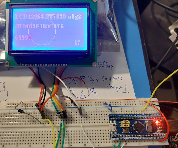
Any WS2811 RGB product should work with this source code / method, I am using a RGB LCD screen, It's made by Makerbase and made for 3D printer / Marlin firmware to use, originally. Since I don't have any RGB LED strip, this RGB LED is a very good test candidate.
In case you have the same product and want to try it, the RGB data pin is LCD_D5, the 2nd pin above 5V.
( BTW Not all 3D printer RGB LCD products use WS2811, some product simply use 3 pin to control R and G and B leds, so no WS2811 on PCB, ie some older version of FySetc; some newer version like 2.1 use WS2811 )
IC Signals and Operation

MCU only sends signal D1 to the first IC, and all the signals and data only go to this first IC. The data contain all data for all 3 RGB LEDs.
The 1st WS2811 receives the all RGB LEDs Data and only use 1st RGB data to control the 1st RGB, and eat the 1st data then send the rest Data to 2nd WS2811 IC(D2). It doesn't need to send 1st RGB data to 2nd IC since no other IC need the 1st RGB Led's data.
The 2nd WS2811 receives the processed data from 1st IC(D2), contain 2nd and 3rd RGB LED data. 2nd IC use the 2nd data to control the 2nd RGB Led and eat the 2nd data and send the rest data to 3rd IC(D3).
And at last the 3rd WS2811 IC receives the 3rd RGB data and use it to control the 3rd RGB LED.
WS2811 datasheet link
In this test we will use software way to toggle the stm32 GPIO to send the signal. Only one GPIO is needed, just a regular one, no I2C, no SPI, just a normal one.
Time and Precision Delay in 100s nano seconds level
The difficult part is the timing. Because we need accurate delay functions to delay about 300 nano seconds and 700nano seconds. The stm32CubeIDE has a standard HAL_Delay() to delay N milliseconds , which is not useful in these cases.
Also the standard GPIO write high / low functions are not useful as well, because the same reason - too slow. Can't use : HAL_GPIO_WritePin()
How to properly delay certain short time: We use __NOP() and #define. We must use #define and not function, since the function itself uses a lot of time. If we use a function and for loop to delay 100nano...it delay about 900nanos. So function is totally not useful, even inline keyword doesn't help.
The solution is to use define, and with the help of oscilloscope to measure the time between rise and fall of the GPIO value.
Once we have a precise delay_100nanosec() "function", we can define other precise delay_200nano, 300nao, 500nano functions (all using #define, not actual functions)
How to make a precise delay 100 nanosecond "function", it's too short, so we can test the delay 1000 nanos function, it's much longer so it's easily measurable, and if it's accurate enough, the delay 100nano function is accurate enough.
With the help of oscilloscope and low level GPIO function, we can do it...right , the low level GPIO functions only, HAL_GPIO_WritePin() can't work since it takes way too long time (900nanos by itself).
GPIOA->BSRR = PROBE_Pin; // Set the Pin High
GPIOA->BSRR  = (uint32_t) PROBE_Pin << 16u; // Set the Pin LOW
Now lets test delay_1000nanos function, and add or remove the NOP in delay_100nano() to adjust the delay time, until it's accurate enough.

According to the oscilloscope, 7 nop in the delay_100nano seems accurate enough.
Then we can also test delay_200nano() delay_300nano() delay_500nanos(), they should be all correct as well.
The RGB data signal to WS2811 IC
The data is not super complicated, each RGB takes R - 8bits or one byte, G and B so total 24bits or 3 bytes. So assume we have 3 RGB Leds, we will send RGB1, RGB2, RGB3 to IC1.
For each RGB data, as mentioned, 3 bytes.
For each byte, we send 8 bits.
for each bit, we send a 0 code if it's 0, or we send a 1 code, if it's 1.
The 0 code

The 0 code is set GPIO high for about 220nanosec to 380nanosec, and set GPIO low for 580nanosec to 1000nanosec. That's why we need precise delay to the 100nanoseconds. Especially for the 0 code high delay time. The 0 code high is the shortest among all codes, only 220ns to 380ns, precision is needed. The other codes are much easier, just 600nano to 1000nanosec.
So we can easily define function to send 0 code, so it's basically :
1 gpio high 2 delay 400nano 3 gpio low 4 delay 600nano
with oscilloscope's help we can accurate measure the high time and low time, also due to other overhead after the function call, we need to reduce the delay for gpio low time delay. As long as the high time and low time are in the allowed range, the 0 code is valid and the IC can accept it.

source code to send 0 code:
Send 1 code to IC
Sending 1 code is similar, only the high time is a bit longer, the same as the low time. ( 0 code and 1 code's low time is about the same, 700nanos to 1000nanos. )
Using above code we can send it, also measure the time using oscilloscope, we can confirm the suitable delay time.

The RESET CODE
After we send RGB (24bit) RGB (24bits) RGB(24bits) for 3 Leds, we need to send the reset code to end the signal, which is the easiest thing in the world, just GPIO low for 300+micro sec, which is much much longer than all the previous nano seconds.
Without this reset code, if we send the 4th RGB data, the ICs don't know this is the 1st RGB data, and will think this is for the 4th RGB.
Now we can send different color to all the RGBs, with a bit more of software work we can even send different color to different Leds. which is easy.
Send different colors to different RGB LEDs
we could easily use a array to hold 3 (or N) RGB data, and send this to IC and reset.
also we can define more functions to dim the light brightness, ON OFF functions etc.
MCU Time Usage
Note that the IC is send once and forget, setting the light is a one time thing. For example, if we send Red, Green, Blue color to the IC, MCU sends it once. the IC keeps the color, MCU can then forget about the IC, don't need to send anything again, until next time the MCU need to change the color or turn LED ON or OFF.
That means, if we don't need to keep changing the color, setting color for the RGB Led is not a CPU consuming task, since it doesn't need MCU to keep running. Therefore, DMA is not needed in many cases, using software way to toggle GPIO is good enough and simple enough.
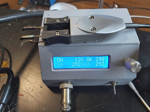
Finally, it's working
I am using this RGB LCD screen, it has 3 WS2811 ICs and 3 RGB LED. one is for screen back light, two are under the rotary encoder.


Source Code
As usual I am using C++ because it can better help me to organize all the variables and functions.

Comments
Post a Comment