DIY Weller Solder Tweezers Controller
DIY Weller Soldering Controller for
desoldering tweezer
Project Objectives:
Make a low cost soldering station for Weller solder tweezers.
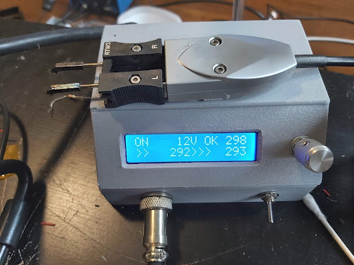
Finished product:
Background:
I so happen to have a used Weller desoldering tweezers, obviously I can't use it by itself, so I thought about buying a weller soldering station, oh, the price is surprisingly high, a few hundred dollars to one thousand dollars....so, buying is not an option, not to me.
So I did some investigation, and realized that making our own DIY weller soldering controller is really not that difficult. There are already some people did that, and there are some useful information about the handle schematics and thermocouple info. However some of their design choices could be better.
Anyway, let me make one, with some awesome features.
Feature List:
- A nice display of LCD screen1602 (16 characters , 2 lines). It's just about $3 dollars, use I2C to communicate to host MCU. It should show target temperature, current temperature, and PWM status.
- Use low cost and popular MCU Arduino Nano, I choose nano, because it has USB connector, while Arduino Uno is too large, Arduino pro mini works but it has no USB connector, not extremely convenient when prototyping.
- Use rotary encoder for GUI control.
- reasonable safety feature: in case anything goes wrong, or user forget to shutdown the soldering station, it should shut itself down.
- Weller desoldering tweezers have a hall effect sensor, and the weller handle rest has a magnet, so the tweezers controller can detect if it'son the handle rest, so to enter standby mode. (need to make our own handle rest )
- To get environment temperature from the sensor inside the handle, KTY82 110.
- buzzer sound
- Low cost (about < 10$ )
Part List:
All parts are low cost and easy to get
- LCD1602 with I2C adapter. so we only need two GPIO pins from the Arduino MCU, for I2C bus.


- Arduino nano However the original Arduino nano from arduino.cc store is not that cheap, it's $20$....not so low, luckily we can choose other low cost arduino nano hardware. Noted that a much more powerful MCU development board Raspberry Pi Pico, a genuine one, is only $5.

- OpAmp, MCP6004 or other similar type. most opamp have the same footprint, so it's easy to switch to other brand or type. I so happen to have a few MCP6004, so I use it.
- a magnet for detecting handle on rest, auto shutdown.
- aviation plug connector, 6 pins (2 heaters, 2 channel of thermocouple, Gnd, Earth ). Remove the special weller connector from the handle, use this kind of standard plug.
- DC power supply 12V 4A.
- LDO 5V
- other low cost misc and common parts like pin headers, active buzzer, resistors, capacitors

Theory of Operation
Schematics:


Software:
software is the heart here.
https://github.com/ntchris/arduino/tree/master/DIY_solderStation
A few key points here:
Thermocouple temperature conversion:
I am using binary search to find out thermocouple 's temperature, because it's fast. I made a thermocouple temperature voltage lookup table according to the thermocouple's data. To make it faster, I used a Excel spreadsheet to calculate all the ADC values first, and use the Integers in the lookup table, so Arduino won't have to calculate anything in the PID 20Hz algorithm. It just need to read the ADC from opAmp and search the closest one in the lookup table. Otherwise the slow Arduino need to calculate a lot temperature voltage conversion (from/to thermocouple mV to opAmp to ADC integer etc.) for 20 times per second, for each size of the tweezers. So this is a lot of saving. Calculate once, use many times is the key.
static unsigned int DiyWellerSolderStation::TCAdcIntLookupTable[] =
{ 0, 14, 28, 42, 57,   72, 87, 103, 118, 134,   150, 167, 183, 200, 217,   234, 251, 269, 286, 304,   322, 340, 358, 376, 394,
  412, 431, 449, 467, 486,   504, 523, 541, 560, 578,  597, 615, 634, 652, 670,   689, 707, 725, 743, 761,
  778, 796, 813, 831, 848,  865
};
Binary search the lookup table. Maybe this is a overkill...but I did it anyway...because I think voltage per C is not accurate enough.
// using TCAdcIntLookupTable, recursive binary search
// return the index that table[index] < value < table[index+1]
// table values must be in small to large order
// if value is too large, return last index.
// if value is too small, return first index.
int DiyWellerSolderStation::valueToLookupTableIndex(int value, int startindex, int endindex)
{
int index;
if ( ( endindex - startindex ) <= 1)
{
//end of search
return startindex;
}
if (value <= DiyWellerSolderStation::TCAdcIntLookupTable[startindex])
{
return startindex;
} else if ( value >= TCAdcIntLookupTable[endindex] )
{
return endindex;
}
int midindex = (startindex + endindex) / 2;
int midValue = DiyWellerSolderStation::TCAdcIntLookupTable[midindex];
if ( value <= midValue )
{
index = valueToLookupTableIndex(value, startindex, midindex);
} else // value > midValue
{
index = DiyWellerSolderStation::valueToLookupTableIndex(value, midindex, endindex);
}
return index;
}
Environment temperature from temperature sensor Kty82/110.
thermocouple can only get the difference, we still need to apply the environment temperature from the sensor inside the tweezers. This doesn't need to be very accurate, I think.
so just make things easier, the resistance of the sensor is not linear but close enough, so just do in a few different temperature ranges, <10C, <20C <30C etc.
PID algorithm
luckily we have pid library - FastPID in arduino already, library just we need to arrange the time to call it in the design frequency.
Rotary encoder
rotary encoder is a mechanical switch, so it has a bad bouncing problem, we could do debouncing in software or hardware. If do it in software, while it's trigger we need to wait and ignore if it's state changes too fast. this is a relatively bad solution, it wasted MCU time and unneccessarily increase the complexity of the software side. On the other hand, doing the debouncing in hardware side is cheap and easy, just just a resistor and a capacitor for each channel.Also I already have a rotary encoder library created, so just use it.It uses pin change interrupt to process the encoder signals, so it very fast and responsive.superRotaryEncoder library and source code:
LCD1602 driver
For LCD1602 driver, can use LiquidCrystal_I2C library.
Plastic Case
Plastic Case
Fusion360 to design the model and 3D print.
To Be Improved in future version:
Hardware side:
To Be Improved in future version:
Hardware side:
1. to remove some optional capacitors around the opAmp.
2. make power supply flexible from 20V to 12V.
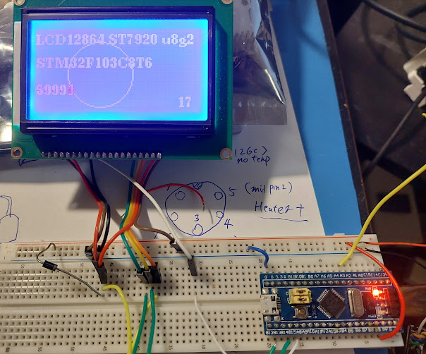
3. maybe consider use stm32 or Raspberry Pi pico
4. use smaller mosfet to reduce the pcb size
5. use MCU and not the mcu development module to reduce pcb size.
6. reduce the pcb size.
Software side:
Software side:
1 rotary encode fast rotation means larger temperature step.
2 standby mode (lower temperature) and sleep mode(completely shutdown), currently only shutdown.
3 more user setting about PID, standby temperature, sleep timer etc.

Nice project! Can this ber used for a T12 iron as well?
ReplyDeleteThis comment has been removed by the author.
DeleteThanks! But no, the Weller twizzlers is quite different from the t12, working voltage 12v vs 24v, very different sensors and pins etc. The best way to use t12 series is to buy a 50-100$ ksger or quicko station, or just buy the PCB , about 20$. Designing one's own hw pcb for t12 is also a good idea, because ksger's hw design has some flaws, in my opinion.
DeleteThanks for the reply! I will try to find a suitable DIY project for T12 or a JBC handle.
ReplyDeleteHi, Interested in this project. Do you have the latest pcb_gerber file? The one in github is 2 year old. Thanks
ReplyDeletethanks for your question. no , there is no updated version, since I haven't worked on it for quite long time. But if you ask me if anything can be improved, I think there are a few:
Delete1. use a more modern MCU, like stm32, or raspberry pi pico.
2. use a two channel pmosfet to replace two large mosfet to downsize the whole PCB a bit.
3. use a larger LCD screen to make it look better, maybe LCD12864, or LCD2004 ( should be easier, i2c, only character text)