Using 3D Printer LCD module RGB MiniLCD12864V3 Part 1 Intro
Using 3D Printer LCD module RGB MiniLCD12864V3
Part 1 - Intro
MiniLCD12864V3, a common 3DPrinter DIY module
There are quite a few low cost LCD modules in the market, the price is only about 12$ each, it contains a 2.2inch size mono LCD, resolution is 128X64, which has beautiful RGB backlight, and a rotary decoder (rotate left, right, button press), and another button, and a buzzer, also on the back there is a SD card slot.
They are quite popular in the DIY 3D printer community, they use two 10pins ribbon cables /connectors to connect to some 3D printer main controller boards. They are supported by Marlin2.0 firmware.


Back of the module. There is a buzzer, two EXP1-2 10 pins connectors, 3 RGB IC, a level shifter IC, a 5V to 3.3V regulator, and a SD card slot.
These are very common components for many many DIY projects, especially the buzzer, LCD and rotary encoder. If we can use this kind of modules, then it would be much easier when we make our own DIY projects.
miniLCD12864 module Feature List:
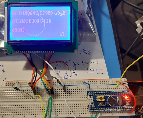
- Mono LCD 128X64 of size 2.2inch, SPI interface, controller is ST7567. (u8g2 supports)
- Rotary encoder.
- RGB neopixel. There are 3X RGB LEDs, one for back light of the LCD screen, two for rotary encoder. There are 3X RGB controller IC WS2811.
- Active Buzzer with transistor
- SD card slot
- Built-in level shifter, most signal shift down to 3.3V. So module works for 3.3V devices like Stm32 and 5V devices like Arduino.
- Built-in regulator 5V to 3.3V, so only 5V power supply is needed for the module.
- 2X ribbon cables are included.
- Two buttons, one in rotary encoder, one regular button.
There are 3 makers for such module as I am aware of, FySetc(original?), Makerbase, BigTree, design are slightly different, price are different depends the maker and where you buy it from, but the connectors are mostly the same, after all, they must work with those 3D printer main controller board.
More info about them in GITHUB: Fysetc, Makerbase , there are design notes and schematics etc.
( Note, Fysetc V2.1 has rgb function, earlier versions don't use WS2811 ICs. )
Pro and Cons for using these LCD modules
Pros:
- Cheaper than making by ourselves. they are mass production products. If we buy all different parts(usually we cannot buy just 1)...shipping and PCB etc...the cost cannot be lower than buying this.
- Easy to use, we don't need to design and make, test and modify the design, solder all parts, test, find problems, remake PCB, solder again, test again, and possibly change the design again...This time consuming process cannot be easy. So, we could just buy and use, they are already verified by many users and 3D printer main boards.
- Design once, use many times. Once we know how to use these modules, we can use them easily in many different DIY projects.
- This module is feature rich, component rich. The LCD is not small, rotary encoder can be used in many user interface needed projects....and RGB
- Active buzzer(with transistor). Most MCU GPIO pin can easily drive the buzzer, and it's easy to trigger the sound( just GPIO drive high)
- The LCD uses ST7567 controller, the speed is quite fast, tested 4Mbit and above SPI speed, works well. my FPS test can reach 40+, without DMA.
- RGB backlight for LCD screen, very beautiful, I don't see a lot of LCD has this feature.
Cons:
- Some design decisions in those modules could be questionable. (But that can be easily changed, by removing one or two resistors, hopefully.) some Pins are 5V, must be very careful when using them with stm32. Some button debounce capacitors are not there, so we must add them in our design, or use software debounce.
- The buzzer is active one, even though it's easy to use, but it's not a passive buzzer, so it cannot play any random musical tones. Can only play a plain and boring beep tone.
- The two 10pin connectors on ribbon cable could be too large for some design.
- The LCD controller need DC (data-command) Pin, so there is one more pin to use, and it's much more difficult to use DMA to do batch data transfer. But I guess it's quite common in today's LCD screen, also DMA is less necessary since the speed is already fast (only 4ms to sendbuffer)
- RGB backlight for LCD screen, so it cannot be easily turned on by simply connecting 5V, we must send some meaningful data to the RGB pin to drive the RGB ic, this could be a little bit challenging.
So, it's good if we can use them for our general DIY projects, (most likely non-3D printer). Can we?
Yes, we can.
Ribbon Cable Connector Interface
Connector pins definition could be slightly different for different modules from different vendors/makers. I am using Makerbase's MiniLCD12864V3. So this is for Makerbase's module:

If we open Makerbase's source code info page, the pin numbers could be different from the Marlin source code or Fysetc's. To make things easier to understand and reduce the chance of error, let's use the marlin's pin#, as the blue numbers in above picture.
Here is the Pin# definition:
EXP1:
Marlin PIN10: Buzzer: BEEPER –1 non-pwm. High to trigger.
Marlin PIN9: Encoder Button, better remove R3 (pullup 5V)
Marlin PIN8: LCD CS ( low to enable LCD, keep low should work if not using SD card), SD and LCD use same SPI bus, so when use both, LCD CS and SD CS must connect to MCU pins.
Marlin PIN7: LCD RS, DC Data – Command. Must connect to MCU and use it.
Marlin PIN6: LCD_D4: LCD Reset, useful in many cases especially when debug, can add a 10k-50k R17.
Marlin PIN5: LCD_D5 : RGB data merlin pin5, MKS Pin6 – LCD_D5 (2nd pin away from 5V)
Marlin PIN4: LCD_D6 : no use.
Marlin PIN3: LCD_D7 : no use.
Marlin PIN2: GND
Marlin
PIN1: 5V power supply for the module
EXP2:
Marlin Pin10 SPI MISO – SD card master in slave out (SD card read)
Marlin Pin9
SPI SCK – SD card and LCD share. SPI SCK
Marlin Pin8
ENC1 no cap debounce needed, but can add. Must MCU input-pullup
Marlin Pin7 SD card CS, pull high to disable SD card if not use.
Marlin Pin6
ENC2 no cap debounce needed, but can add. Must MCU input-pullup
Marlin PIN5 MOSI – SD card and LCD share, Master Out Slave In, LCD write/SD write.
Marlin PIN4
SD Card detect, MCU input pullup, insert: short to GND, better remove R14
(pullup to 5V)
Marlin
PIN3 Button (the "reset button") , just a regular button, has nothing to do with "reset", MCU input pullup, pressed = GND ( no
debounce capacitor) Most 3D printer main controller board use this button to "reset".
Marlin PIN2 GND
Marlin PIN1 Not Connected ( no 3.3V, LCD module missing a R , add a 0R if needed)
All pins required by LCD are in bold font in above list.
LCD CS and RESET pins are optional for LCD in development or final "product" if we need simplify the debug setup.
Questionable Design Decisions and fix:
In my opinion there are two things need to be fixed in the Makerbase's module.
- Encoder button pullup connected to 5V, it creates an unnecessary risk to stm32.

The fix: Remove R3. Instead, in MCU pin setting, use input pullup mode; or, add our own pullup to 3.3V if needed.

- SD card detect pin pull up connected to 5V, it creates an unnecessary risk to stm32.

The fix: remove R14. MCU pin use input pullup.

Even though STM32 can take 5V under the right circumstances, but not always, and not every gpio pins, so providing 5V to stm32 is very risky, and unnecessary at all. It would be easier just to remove above 2 pullup to 5V resistors.
For more info about 5V and Stm32, check
AN4899 Application note STM32 microcontroller GPIO hardware settings and low-power consumption link
Finding the right PINs
It's important to get the right pins in the ribbon cable, otherwise, not only our project won't work, it's also very possible to damage the MCU gpios.
The first step is to find the GND and 5V in EXP1.
- To find GND: is easy, just use a regular multi-meter Resistance function to measure the Gnd PIN and SD Card metal slot. it should be about 0 R or beep~~~
- To find 5V, use multimeter Resistance function to measure the ribbon cable 5V pin and regulator 1117's right pin, (left pin is GND, middle pin is 3.3V).
- Beeper, in the same row with GND, in the very far end. Now we can do the first simple test to make use of this LCD module, make some Beep sound: we can provide 5V and GND to EXP1, and 5V to beeper Pin. we should hear beeper sound.
For EXP2,
Find GND pin first using the same way above.
3.3V Pin is likely not connected, so do not try to verify it. just leave it not connected.
Insert a SD card, we should measure the SD-Det pin shorted to GND, remove it, it's not connected to GND, if above pullup resistor is removed, or with some K resistance if pullup resistor is still there.
Base on the GND/5V/SD Det, we now can identify all the rest of Pins in EXP1 and EXP2.
Once again, different maker vender or different hardware design version are different.
Always check maker's design document and carefully verify all the Pins before use them.
All useful pins are connected:

Indeed it's a bit messy...but hopefully once we have our PCB ready, things should look much cleaner.
After all, we need to control so many components.
Part2 Using the LCD with U8G2
https://superdiyprojects.blogspot.com/2022/10/using-3d-printer-lcd-module-rgb_30.html
Using 3D Printer LCD module RGB MiniLCD12864V3 Part 2 LCD u8g2

Comments
Post a Comment