Posts

ERCF Easy Optical Encoder Module

Image
  ERCF Easy Optical Encoder Module For ERCF: to make it easier for everyone to use a transmissive optical sensor in one simple sentence, a DIY friendly, a much cheaper and easier blinky sensor module for ERCF. What is this: for ERCF (Enraged Rabbit Carrot Feeder Multiple Material System for Voron or alike 3D printers) replace the original reflective optical sensor which is quite not reliable. so mneuhaus made a transmissive optical sensor encoder called Binky, which should provide a much more reliable encoder functions/counter. https://github.com/mneuhaus/EnragedRabbitProject/tree/main/usermods/Binky What is a transmissive optical sensor an optical sensor, or photo sensor, slot type, like SX1103, or ITR9608. It has a infrared diode and a receiver, if an object blocks the infrared light, the receiver detects it and triggers/send a signal. However, there are still some problems remains with Binky module, blinky PCB is quite expensive, plus shipping (international!) and tax, I&

ERCF Hardware and Software Config and Setting Notes for BTT BigTreeTech ERCF CAN BUS board

Image
ERCF Hardware and Software Config and Setting Notes for BTT BigTreeTech ERCF CAN BUS board BTT calls this board "BIGTREETECH MMB CAN V1.0 Board Enraged Rabbit Carrot Feeder ERCF Control Board CAN Bus" btt_ercf_canbus.jpg What is it I assume you all know what is this and what this for? If not, this is a expansion board for Voron printer or alike to let it work with Enraged Rabbit multi material system (ERCF) Similar product in market is Mellow's CanBus ERCF board. Fysetc's ERCF board only supports USB connection ( unless now they have newer product to support CanBus, I didn't check) How good, why good What's special about this BTT ercf board is, and what make me buy it: It use BTT's EZ stepper motor driver, which is like a mini PCIE graphic card, looks cool It supports CanBus for ERCF, which makes wiring easier. It has a lot of expansion socket, 4 motor slots (ERCF only need 2), and tons of gpio. potentially we can make some new crazy features. Product

ERCF Hardware and Software Config and Setting Notes for Mellow ERCF CAN BUS board

Image
ERCF Hardware and Software Config and Setting Notes for Mellow ERCF CAN BUS board ERCF = Enraged Rabbit Carrot Feeder Voron Printers like 2.4. Fysetc and Mellow is/are 3D printer parts/electronics vendor(s) This is the Mellow ERCF canbus board There are so many combination in the configuration when using ERCF, see below..., so I think a HW/SW config note is necessary. A few key points in the config: Using SensorLess Selector Homing Mellow ERCF Board supporting Canbus Using CANBUS (not USB) to Klipper mother board My Klipper mother board is Optopus but it shouldn't matter Using HappyHare ERCF Software V3 ( https://github.com/moggieuk/ERCF-Software-V3 ). ( original ERCF fw has quite different config file) Tool head has no hallsensor or mechanical microswitch sensor, since not needed ( but PTFE Pneumatic fitting to lock the PTFE (2.5 ID mm/4mm OD) is needed since ptfe tube must be locked tight to the tool head. Mellow ERCF Canbus Board preparation Hardware Jumper config 1 Do NOT

STM32 GPIO PWM Simple Example for Blackpill/Bluepill dev board

Image
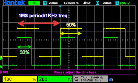
 STM32 GPIO PWM Simple Example   Arduino hardware and Arduino IDE can easily let GPIO pin to work on PWM mode, simplyuse analogWrite() , ie analogWrite (pin, 128); simple and easy.   Unfortunately STM32F### hardware and STM32CubeIDE need quite a lot more work to achieve this. Here is some simple steps to let STM32F401 or STM32F103 to set GPIO to work on PWM mode on the fly, as simple as I can make it to be.  To be able to see the GPIO pins's PWM signal, a oscilloscope is needed, but any cheap one should work, including those 30$ low cost ones. 😜 Certain multi-meter can see pwm frequency and PWM % as well, but we cannot see the wave form. Choose the Right Pin and Timer. STM32 Pin PWM mode requires TIMER to support it.  We must choose the pin(s) or timer carefully, certain pins only work with certain timer; certain timer can only work with certain pins. That means, if our project uses a Timer for other purpose, then certain pins cannot be used for PWM.  How Many PWM GPIO Pins do we

Using 3D Printer LCD module RGB MiniLCD12864V3 Part 4 Test App

Image
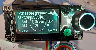
Using 3D Printer LCD module RGB MiniLCD12864V3 Part 4 Test App     Now we can use all parts in the module. 1 Part1 Intro introduction to the module pros and cons and ribbon cable pin definition. 2 RGB backlight   enabling the RGB backlight for the LCD screen 3 Part2 using LCD with SPI and U8G2   LCD wire connection, SPI setting, and using U8G2 lib to draw on the LCD. 4 Part3 Using the rotary encoder    also use beeper and buttons.   Now we can make "full" use of this lcd module, except for the SD card, I guess this can wait, since not many DIY project really need a SD card... With all these feature enabled, we now can make a test app. Test App to do list: Press any button, buzzer beeps. To use rotary encoder to change the LCD RGB backlight, and apply to the LCD backlight. Make a simple GUI on the LCD screen, make it work with the rotary encoder. Video https://youtu.be/t1N9a9b_4fA   Source code https://github.com/ntchris/stm8_stm32/tree/master/bluepill_makerbase_miniLCD12864_

Using 3D Printer LCD module RGB MiniLCD12864V3 Part 3 Rotary Encoder and Stm32

Image
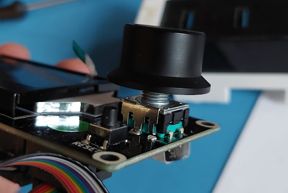
Using 3D Printer LCD module RGB MiniLCD12864V3 Part 3 Rotary Encoder and Stm32   Very Easy There is a Rotary encoder in this LCD module, which is very useful in many very projects. It's quite easy to work with rotary encoder in Arduino hardware and Arduino IDE environment. But guess what, it's even much easier to work with rotary encoder in STM32CubeIDE for STM32 MCUs. Many Arduino implementation need to keep reading the GPIO value to act fast reaction for acceptable user experience, ...or,  it need to make use of Port Change interrupt due to lack of external interrupt in Arduino hardware. None of this is necessary in STM32 and STM32CUBEIDE. Also, there is no rotary left and right debounce capacitor on the module, it's nice to have them, but still, without them, it works perfectly, since STM32 has built in software debounce mechanism. More info about STM32 Timer link  Ribbon Cable Pin Connection EXP1 Pin9 ENC_BTN  the press button EXP2 Pin8 and Pin6 BTN_ENC1 and BTN_ENC2 O