STM32 GPIO PWM Simple Example for Blackpill/Bluepill dev board
STM32 GPIO PWM Simple Example
Arduino hardware and Arduino IDE can easily let GPIO pin to work on PWM mode, simplyuse analogWrite(), ie analogWrite(pin, 128); simple and easy.

Unfortunately STM32F### hardware and STM32CubeIDE need quite a lot more work to achieve this.
Here is some simple steps to let STM32F401 or STM32F103 to set GPIO to work on PWM mode on the fly, as simple as I can make it to be.
To be able to see the GPIO pins's PWM signal, a oscilloscope is needed, but any cheap one should work, including those 30$ low cost ones. 😜

Choose the Right Pin and Timer.
STM32 Pin PWM mode requires TIMER to support it. We must choose the pin(s) or timer carefully, certain pins only work with certain timer; certain timer can only work with certain pins. That means, if our project uses a Timer for other purpose, then certain pins cannot be used for PWM.
How Many PWM GPIO Pins do we need?
Certain Timer only supports one GPIO pin, some other timers supports up to 4 GPIO pins.
For exampale, STM32F401 (Blackpill), TIM10 (PB8) and TIM11(PB9) only supports one GPIO pins.
TIM9 support two GPIO Pins PA2 and PA3.
TIM3 supports 4 GPIO pins - PA6, PA7, PB0, PB1.
If we need, we can config TIMER3 to control 4 different GPIO pins at the same time, they must run at the same frequency, but can have different PWM value.
Choose the Pins for this test
We choose PB0 and PB1 for this test, so must use TIM3. Let TIM3 to control PM0 and PB1 to output PWM signal at the same time.
Timer Setting for Pins
In STM32CubeIDE, Choose Timer3,
Activate Internal Clock, choose Channel3: PWM Generation for PB0, and Channel4 Generation for PB1. Each channel controls one GPIO pin.

Set the Right Frequency for the Timer
One timer can run at a fixed frequency, which can be easily set in the STM32CUBEIDE. I assume in many use cases we only require the GPIO pins to run at a fixed frequency, let's use 1KHz in this test.
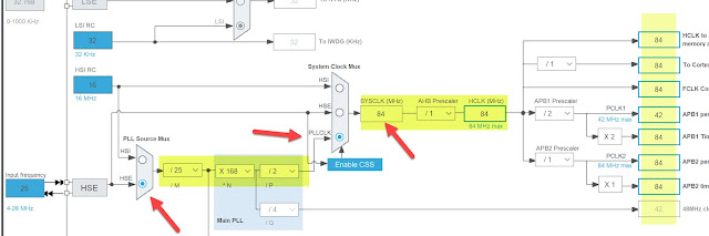
Confirm the System clock speed first
Reason: it's needed when we set the timer's clock.
Blackpill STM32F401CCU6: 84MHz Max , Bluepill STM32F103C8T6 72Mhz Max.
For example, Blackpill STM32F401 system clock setting:
For more info we can refer to MCU datasheet, chapter Functional Overview, Timers and watchdogs, which timer works for which pins etc.

Set Timer Frequency for 1KHz
In this test we will set the PWM to run at 1KHz
So in Tim3 setting, 84MHz / 1KHz/ 255 = 329 :
set Prescaler = 329 (330-1), and Counter Period = 255-1 ( this is for the full PWM period) , so if we set 25, it's 10% PWM, we set 128, it's 50% PWM. 255 is perfect for PWM Max value, which is the same as Arduino, and perfect for Uint8.
To check if the Timer is now running at 1KHz:
84MHz / 329/254=1K

The rest is not important or can be left as default values.

Start the Timer in Software
// define timer constant for easier use, and easily change should we need to
#define TIMER_PWM htim3
#define PWM_OUTPUT1 TIM_CHANNEL_3
#define PWM_OUTPUT2 TIM_CHANNEL_4
Must start timer first, for both channels. before the main loop while(1)
HAL_TIM_PWM_Start(&TIMER_PWM, PWM_OUTPUT1);
HAL_TIM_PWM_Start(&TIMER_PWM, PWM_OUTPUT2);
Set the PWM in Software Code
Option1 Registor and hardcode:
htim3.Instance->CCR3 = pwm;
htim3.Instance->CCR4 = pwm;
so we can set pwm value like this, 128, 255 etc.
CCR3 is for channel3, which is for PB0
CCR4 is for channel4, which is for PB1
Option2 HAL Function
if directly handling register is not ideal, we can use HAL function
__HAL_TIM_SET_COMPARE( &TIMER_PWM, TIM_CHANNEL_3, 85 ); // 255/3=85
__HAL_TIM_SET_COMPARE( &TIMER_PWM, TIM_CHANNEL_4, 128 ); // 50% of 255
We need to provide timer and channel and the pwm value. so we set 33% and 50% for two GPIO pins as above.
That's it, a little bit more than Arduino's analogWrite(), but inthe end, we can achieve different PWM frequency with STM32, and still just one line of code to set the PWM.
We can see both PWM signal are correct, 33% and 50%.

Let oscilloscope measure it, seems right.

Edge value testing
Because we set the Counter Period (Auto Reload Reg) to be 255-1. To make sure when we set 255 PWM value, it's fully turn on instead of 0 ( overflow or other unthinkable strange reasons like many others when we work on mcu and electronics), we can test the Pin's voltage by using a multi-meter. it should measure 3.3V and not 0.
Change PWM on the fly
in the main loop, we keep changing both pins's PWM value, so in oscilloscope we can see the signals keep changing.
Check the video, seems working, both PWM signals keep changing from 0 to 255 ( 0% to 100%)

Comments
Post a Comment