Using 3D Printer LCD module RGB MiniLCD12864V3 Part 3 Rotary Encoder and Stm32
Using 3D Printer LCD module RGB MiniLCD12864V3 Part 3 Rotary Encoder and Stm32

Very Easy
There is a Rotary encoder in this LCD module, which is very useful in many very projects.
It's quite easy to work with rotary encoder in Arduino hardware and Arduino IDE environment.
But guess what, it's even much easier to work with rotary encoder in STM32CubeIDE for STM32 MCUs.
Many Arduino implementation need to keep reading the GPIO value to act fast reaction for acceptable user experience, ...or, it need to make use of Port Change interrupt due to lack of external interrupt in Arduino hardware.
None of this is necessary in STM32 and STM32CUBEIDE.
Also, there is no rotary left and right debounce capacitor on the module, it's nice to have them, but still, without them, it works perfectly, since STM32 has built in software debounce mechanism.
More info about STM32 Timer link
Ribbon Cable Pin Connection
EXP1
Pin9 ENC_BTN the press button
EXP2
Pin8 and Pin6 BTN_ENC1 and BTN_ENC2
Only above 3 pins are needed for rotary encoder and MCU connection.

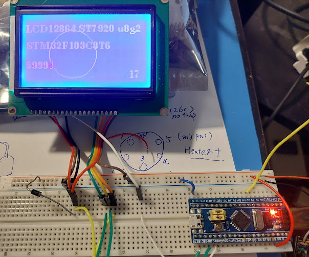
STM32CUBEIDE Pin Setting
Timer setting
This could be a bit counter intuitive in my opinion, just set the timer correctly, we can directly use the rotary encoder. How come a rotary encoder has anything to do with timer ?? but that's the way it is. So just let's set it.
Depends what two PINs we choose for rotary left/right, we need to choose the right stm32 timer.
so let's use PA15 and PB3, then we need to TIMER2 (TIM2)
In Pin Map, choose PA15 and PB3, enable TIM_CH1 and TIM_CH2 mode.
( If we want to use other Pins then must choose another timer, and not every random Pin can be chosen for this purpose. For example, choose PA6 and PA7, then it's TIM3 )
Note, Not to choose GPIO input mode.

Set the timer parameters
Counter Period (AutoReload), 1023, or 65535, should all work.
Encoder mode TI1 and TI2
Rising edge, Input filter 15 for debounce. (even without capacitor, it works)
Set this for both channels 1 and 2.


GPIO pullup, very important
Without pullup, the GPIO read value is random, encoder won't work at all.
STM32 internal pullup is good enough, if still not happy, can always add an external pullup.

Enable Global interrupt for encoder

That's all, not a single line of code is needed.
Using the encoder
without writing a single line of code, rotary encoder now working with stm32.
all we have to now is simply use it in the interrupt handler function.
inside the function HAL_TIM_IC_CaptureCallback()
Each full step turn gives the encoder timer value +4 or -4.
so we can examine the value, and handle it accordingly.
value = __HAL_TIM_GET_COUNTER(htim);
That's all.
Usually we need to further process the value to make use of it.
For example if we need to use the encoder to set a RGB value of 0 - 255, then we can check if the value is 4 less, then it's one step down, we can do RGB--. or the timer value is now 4 more, then we can do the RGB++.
I believe we can ignore all interrupt where the difference is less than 4, these are half steps, meaningless.
The middle button
The encoder button is not part of the STM32 Timer, only the left and right are handled by the Timer.
So the encoder middle button is just a regular button, use GPIO pullup read to handle it.
when pressed, it's shorted to GND.
But we still need interrupt to handle the middle button, otherwise we have to keep reading it, which is not a good idea at all.
To enable interrupt for the button GPIO:
also must enable input-pullup.

Optional capacitor
software debounce (left and right) by ourselves in the code is Not needed at all, stm32 handles it already.
So that's it, that's all we need to make the rotary encoder to work with STM32.
But I believe it's always good to add debounce capacitor like this.

It's good to use capacitor for the rotary button as well, even though it's also can be debounce in the software code, but I think it's easier to just to add a capacitor.

Comments
Post a Comment