Super DIY 2020 Desktop CNC for milling PCB
Super DIY 2020 Desktop CNC for milling PCB
Project objective:
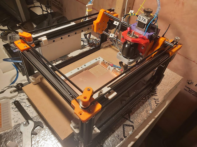
Make a low cost desktop CNC to mill PCB, using standard aluminum 2020 extrusion as frame, and brushless motor as spindle. Since we need to mill PCB, some component's footprint is tiny, so the CNC has to be precise enough to mill trace and clearance of 0.2mm.
The Finished Product:
Back Ground:
I always want to make a desktop CNC to mill custom PCB for rapid prototyping, this project was inspired by some other creative people's CNC designs, specially the ANT team ( https://www.youtube.com/c/TheAntPCBMaker ), however I do have a lot different opinions for some design choices. So after one year's work, I designed, rework, redesigned, reprint, rework again...for many times, finally this Super 2020 desktop CNC is sort of finished.
Design consideration:
- It has to be small enough, as a desktop CNC, it's not for milling large piece of wood, it's made for PCB, the most common PCB size is 10cmX15cm, so the CNC is designed to work with this size of PCB. Since in my country, PCB or copper clad board 's price is extremely expensive, this CNC must not waste too much of the 10X15CM size, the mill area must large enough to cover most of the PCB area.
- Frame material, use aluminum extrusion. The most common size is 2020 (20mm by 20mm). it's low cost and easy to buy different sizes. 4X300mm for Y, 4X250mm for X, 4X100mm for Z frame.
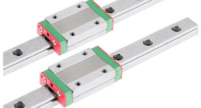
- 2 Linear rails MGN12H 250mm for Y axis
- For X axis, use 8mm rod and 8mm linear bearing LM8LUU (LUU is the the longer size, it's better than the shorter one). Maybe try linear rail on X as wel in futurel)
- Spindle and motor: I choose to use direct drive, and not using any belt, gears, to reduce system complexity, noise and cost.
- Spindle, must use brushless motor and BLDC speed controller. Who wants to use brushed motor in a mini desktop CNC in year 202X anyway. Since the spindle must use a chuck as tool holder, the most common type is ER11 chuck, the smallest and strong enough hole size is 5mm, so our spindle/BLDC motor must have a 5mm output shaft. (There are ER8 5-4mm chuck but could be bit difficult to find. maybe try it in future ?)
- BLDC motor: since our chuck is 5mm so the BLDC must be 5mm shaft. also we could use out runner BLDC motor, they provide larger torque than the same size of in runner motors. Out runner BLDC motor are ussually for hobby RC airplanes while the in-runner BLDC motors are for truck and car RCs. I chose 3542 1000KV BLDC outrunner motor, it has 5mm shaft. But the problem of outrunner motor is it's not so easy to mount, since it's whole outside can is rotating the whole time, while inrunner motor is very easy to mount, just clamp the can. And of course, the motor's cost is very reasonable. The mounting accessories are important, must use them to mount it on the CNC gantry.
- This BLDC motor is quite powerful maybe later I can try using it to mill aluminum pieces. and it's powerful enough not to use any belt or gear to increase torque since it's 1000KV ( lower speed and higher torque, comparing to car in runner motor, they are usually in 3000KV range, meaning higher speed and lower torque)
- BLDC ESC, bldc speed controller. Need to use a hobby drone ESC, hobby RC car/truck ESC works but it's not as good as drone since car esc has a brake function, we don't need brake. Any low cost drone BLDC ESC works well, 10A+ to 20A works fine since the motor doesn't draw much current while milling PCB. The motor draw about less than 2A at 12V while doing full speed free run. Similar products as below all work well, the cost is low, for just about $5-$10.
- CoreXY driver system. CoreXY is quite popular now, many 3D printers are now using this architecture, so I just use it. However it doesn't mean this is the best option for CNC, the XY precision is not high enough in my opinion, but still it's good enough.
- Stepper motor: I chose two NEMA11 50mm height stepper motor for X Y. NEMA11 motor sometimes has a name motor28 because the motor body size is 28mm. The 40mm size nema11 motor may not be powerful enough. Later I realized NEMA11 50mm stepper motor is quite expensive, NEMA14 motor could be a better choice. NEMA17 is too large and too powerful.
- Z axis motor, it must be small and light since it's mount on the gantry, so a smaller NEMA11 30mm motor.
- Belt driver system: GT2 belt , 6mm in size, with glass fibre core(it's better than steel core), 16 teeth pulley and idler. 16teeth pulley gives higher stress to the belt while 20teeth gives less stress, however 20teeth has lower resolution, thus lower precision.
- screws: Using M4 screw to mount the 3D printed part on aluminum extrusion, while the screw hole is not too big, M5 screw hole is too large, M3 screw may not be strong enough.
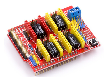
- Micro controller: Arduino Uno and CNC shield and Stepper motor driver. The cnc shield is quite easy to buy and very low cost, it works with a Uno, there is also a version for Nano. They both work.
- Stepper motor driver, 3pcs DRV8825 for x y z. I choose DRV8825, it has a higher resolution (1/32 step ) than the low cost A4498 (1/16 step), while the cost is still very low.
- XYZ limit switch, using mechanic micro switch, what's good is it works on any surface and any part that touches the switch, it's triggered. What's bad about it is it has bouncing problem since it's mechanical switch, more circuit is needed to combat that. On the other hand Optical switch can always trigger reliably, but it's difficult to mount, carefully design parts must be mounted on the gantry to block the optical sensor, this creates a lot of extra work. X limit switch:Y limit switch:
Z limit switch: - Since it's using mechanical micro switch as stopper, I would like to add a optocoupler circuit to deal with isolation and bouncing problem. What it does is:
- Isolation, in winter, the PCB may have high voltage statics problem it may very well damage the Arduino's GPIO pin.
- Debouncing for mechanical switch.
- Added LED light to indicate the XYZ position has reached the limit.
- Added Buzzer sound to indicate the XYZ position has reach the limit, especially for Z, when probing, while the mill cutter touching the PCB, we must not move the gantry in XY, otherwise it will be a disaster, it will destroy both the cutter and PCB. A buzzer warning sound is good for that, it reminds me always lift the gantry a little bit before move in XY. By the way, the optocoupler PCB was milled by this CNC itself.
- Wireless PCB probe ad bed leveling: since it need to mill PCB, probing and auto bed leveling is always needed. traditionally we need to use a alligator clamp on the cutter, it's a lot of work and if we forget it once the cutter/route bit will be damaged. So, there is a way to always connect the BLDC motor/cutter to the micro controller. Connect the probe wire to the bearing, then the route bit is connected to the MCU as well. But the bearing is not always well conductive, a better solution is needed in future.
3D modeling and Printing
All parts are designed in Fusion360 and 3D printed using my PRUSA MK3 3D printer.Material is always PETG.https://github.com/ntchris/grbl/wiki- This release added support for brushless ESC, including brushed ESC and brushless ESC, hobby RC car ESC and drone ESC. The current ESC control signal is 244HZ, should be supported by most of the brushless drone ESC and brushless car ESC. Unfortunately many Brushed ESC do not support this high frequency, they only support 60HZ, so changing config.h file is necessary. the PWM pin is arduino Pin11, the motor PWM pin, if using the red CNC shield, it's the "Z Stop" pin.
- Added new system setting $38 for ESC type, default is 0. Just like changing any other setting, in serial interface, run $38= to set it:
- $38=0, to disable esc, using regular motor, as usual.
- $38=1, to use drone brushless ESC, meaning ESC control signal on time starts from 1ms. This also support brushed ESC, but currently I am using 244HZ for the ESC control signal, which is most likely too high for traditional brushed ESC. in that case you can modify the config file to use 60HZ setting.
- $38=2, to use RC hobby CAR brushless ESC, meaning ESC control signal on time starts from 1.5ms. (<1.5ms is for brake and reverse)
Must disable ESC's brake function ----- more to addPC software: My Heavily Modified BCNC
It works in a safer way than the original BCNC, to protect the cutter and PCB, avoid the cutter to easily hit the PCB and destroy each other; also it can do auto bed levelling in a convenient way: one button ABL. https://github.com/ntchris/bCNC
----- more to addOther Supporting Software
flatcam
to process the gerber file http://flatcam.org/Working Videos:
- CNC doing Home action https://www.youtube.com/watch?v=f3-g-Br7sFg
- CNC moving gantry around https://www.youtube.com/watch?v=ibLaSasCpOY
- CNC BLDC ESC and Motor speed control in the CNC software - BCNC. https://www.youtube.com/watch?v=HXZ1UxKWOw0





Comments
Post a Comment